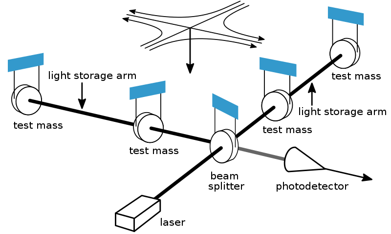
Schematic of the LIGO Detector (Source: Wikimedia Commons)
Interferometric gravitational wave detectors incorporate cutting edge technology from various fields. Glimpses of few such technological marvels that will be used in LIGO-India are provide below.
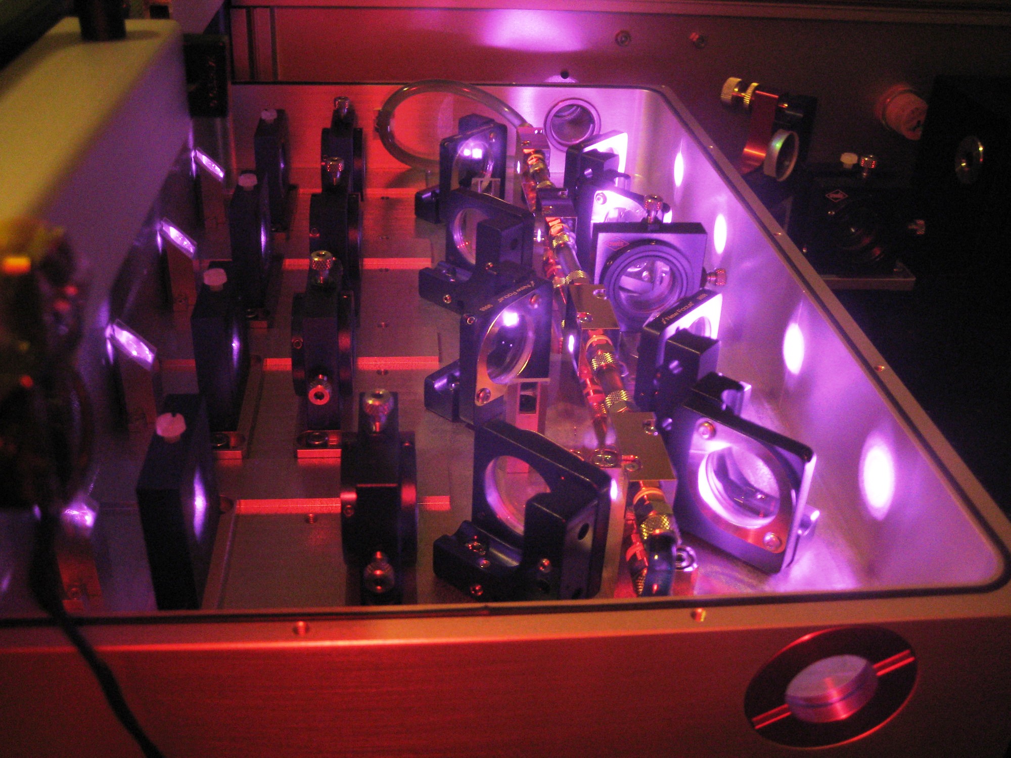
Pre-stabilised Laser (Image: LIGO Lab/Caltech/MIT)
Laser
The LIGO interferometer hosts a laser at the 1064nm target wavelength. A non-planar ring oscillator (NPRO) generates a 2W ‘seed’ beam that is amplified through several stages until it can reach a desired 200W at the output. The entire system is called the pre-stabilized laser system (PSL).
Power stabilization will probably be the most demanding laser stabilization task in future gravitational wave detectors. Technical power noise on the laser can couple via many paths into the gravitational wave channel: asymmetric arms and radiation pressure noise, deviation from the dark fringe, radiation pressure noise. Advanced LIGO requires a relative intensity noise (RIN) of around 10−9/√Hz in the interferometer input beam. The accurate sensing of the needed 500 mW laser power at that location is difficult and the signal is still contaminated by pointing, polarization, and potentially even frequency noise. Ongoing research is needed to understand these couplings and reach the required stabilities.
Optics
The LIGO core optics or test masses are currently made of ultra-high purity fused silica and coated with titania-doped tantala such that they have minimum absorption at the working wavelength of 1064nm. The mirror coatings are also dichroic in that they provide some reflectance at (1064/2) nm = 532 nm which is used for auxiliary measurements. The mirrors are specified to have absorption in the order of 3ppm and figure error in the order of 0.35nm. This is a major challenge for materials research given the size of the mirrors at 34cm in diameter and weighing 40kg.
Coatings research plays a major part of the upgrades that LIGO will undergo in the next few years. Reducing thermal noise of the coatings even further without losing on optical absorption will be the problem that takes centre stage for the next few years. Any improvement that will reduce thermal noise by even a factor of two will contribute immensely as it would correspond to an improvement in the detection rate by a factor of 8.
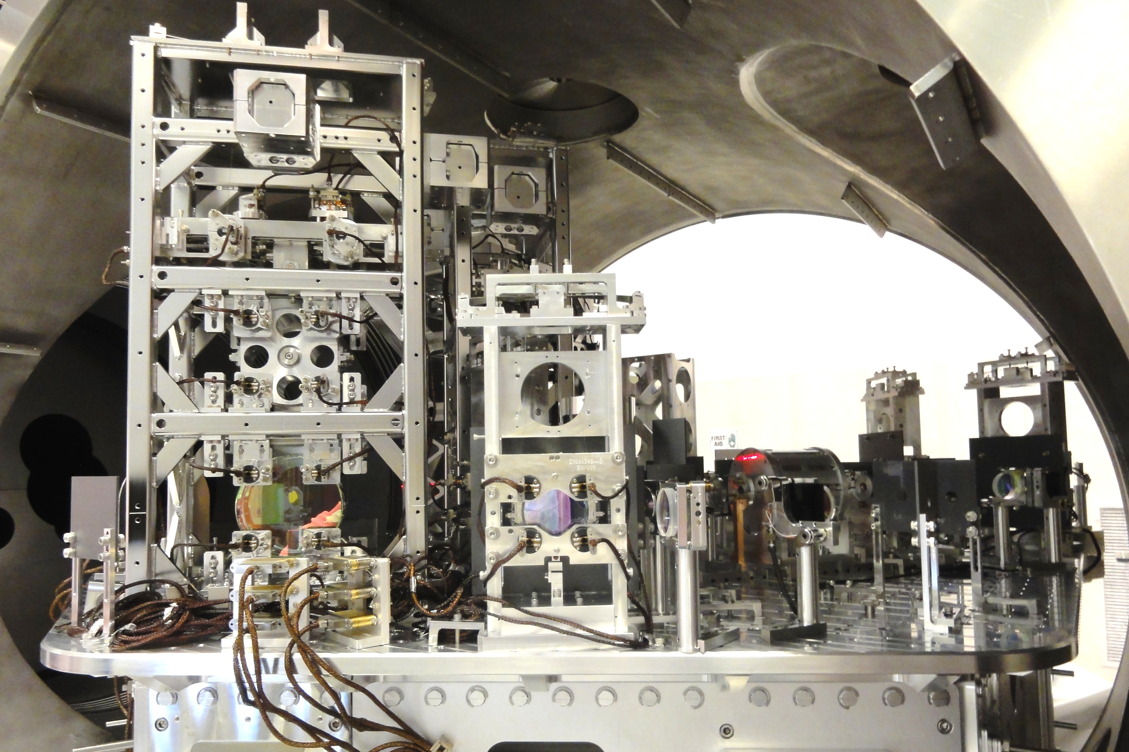
One of the optical tables of LIGO Hanford (Image: LIGO Lab/Caltech/MIT)
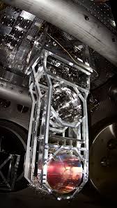
One of the LIGO test masses with suspension (Image: LIGO Lab/Caltech/MIT)
Suspensions and Vibration Isolation Systems
LIGO vibration isolation can be broadly classified as active damping and passive damping systems that together ensure that the detector components are isolated from any external vibration. Active damping systems probe the environment for vibrations at different frequencies using sensors and generate counter movements thereby isolating the instrument from such noise. Passive damping systems include the seismic isolation and suspension sub-systems for the optics in LIGO. It is comprised of three sub-systems: the hydraulic external pre-isolator (HEPI) for low-frequency alignment and control, a two-stage hybrid active & passive isolation platform designed to give a factor of ∼ 1000 attenuation at 10 Hz, and a quadruple pendulum suspension system that provides passive isolation above a few Hz. The final stage of the suspension consists of a 40 kg silica mirror suspended on fused silica fibres to reduce suspension thermal noise.
There is ongoing R&D work to provide incremental improvements to Advanced LIGO to improve performance, enhance robustness, and improve the duty cycle of the aLIGO vibration isolation and suspension. This type of work is designed to be easily incorporated
with the existing detector systems with minimal disruption of the Observatories. These upgrades include work to add additional environmental sensors and incorporate them into the controls, or adding more sophisticated control algorithms to improve performance during unusual environmental conditions, or small mechanical changes to damp vibration modes.
Control Systems
The detectors have relied mostly on classical control theory to maintain its stringent alignment requirements in order to detect gravitational waves. Control of the interferometers requires many Multiple-Input-Multiple-Output (MIMO) control loops closed both locally and globally across the 4-kilometre interferometer arm lengths. LIGO’s control and feedback systems currently operate at 16 kHz.
Several aspects of feedback and controls are already under investigation to improve the near future sensitivity of the detector by reducing the control noise. Bilinear adaptive noise cancellation has been investigated to eliminate certain noise sources from the useful gravitational wave signal. Efforts are underway to use machine learning as a tool for automatic optimization of the interferometer. Various aspects of modern control theory are looked into so that they can be incorporated into control loops in order to save time spent in tuning them by employing just the classical approach.
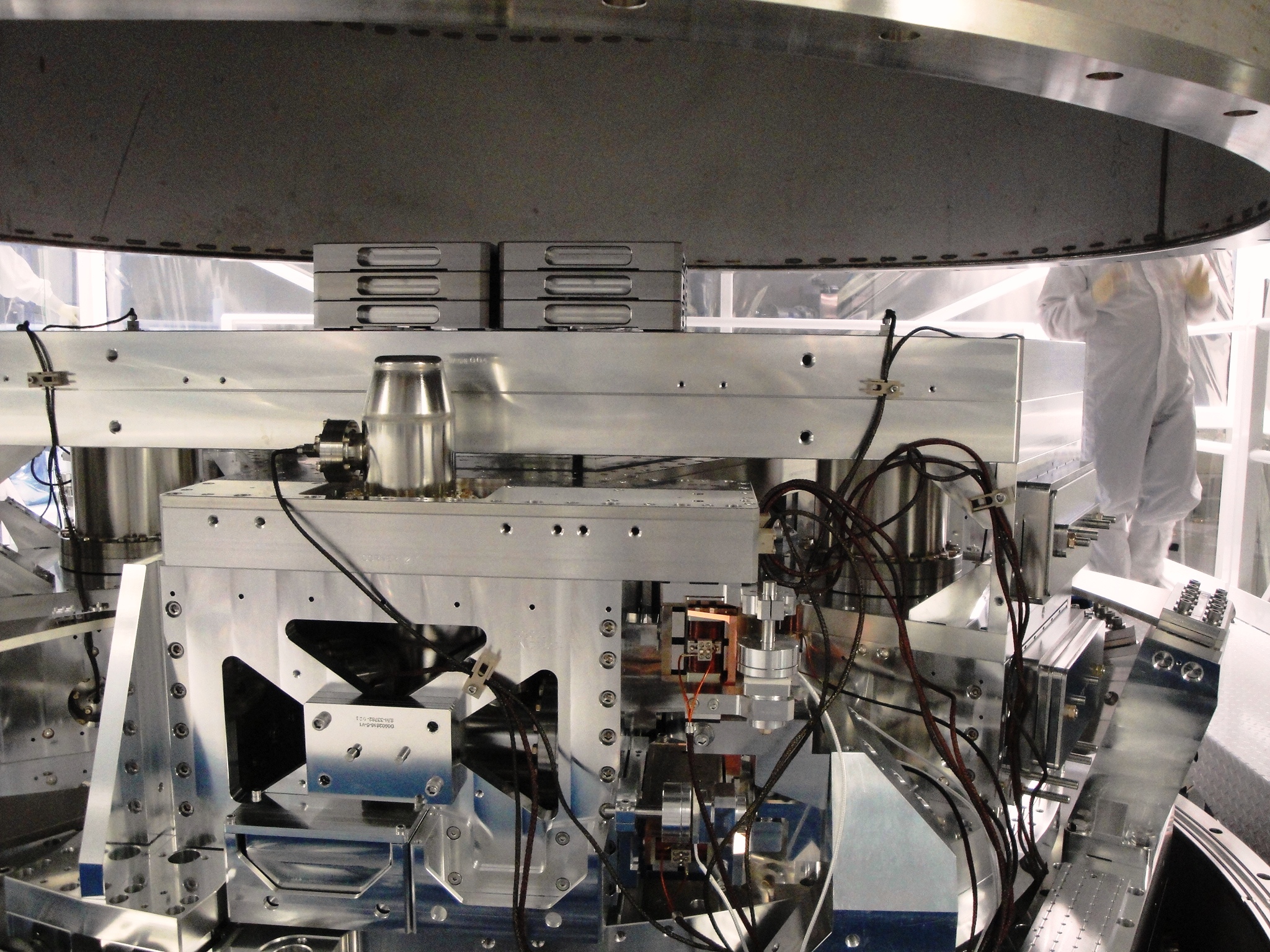
A Basic Symmetric Chamber (BSC) with complex Control System (Image: LIGO Lab/Caltech/MIT)
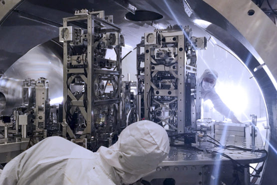
One of the LIGO vacuum chambers with active seismic isolation (Image: LIGO Lab/Caltech/MIT)
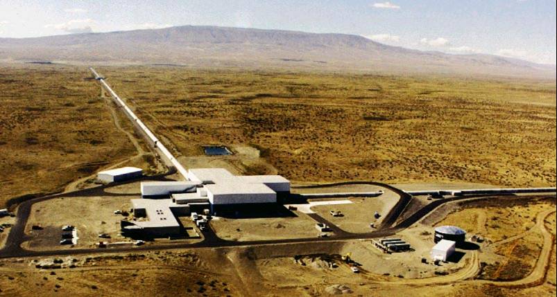
One 4km arm of the LIGO Hanford Observatory (Image: LIGO Lab/Caltech/MIT)
Ultra-high Vacuum
LIGO’s vacuum system is one of the largest sustained vacuum systems and also one of its kind. The detector is maintained at one-trillionth of the atmospheric pressure at sea level. Such ultra-high vacuum becomes necessary to eliminate noise in length changes of the interferometer arm brought by any residual air in the chambers affecting the detection of a passing gravitational wave and also avoid absorption of the laser light by any residual dust or gas molecules thereby causing unwanted scattering.
In order to maintain LIGO’s vacuum pure, everything which is placed inside the UHV, such as the seismic isolation systems, has to be rigorously qualified for outgassing. UHV materials have to be carefully chosen to start with – for example, regular steel is saturated with hydrogen, which seeps out under low pressure, so LIGO’s beam tubes were made from special low outgassing steel. Next, any components destined for the UHV has to be thoroughly cleaned with solvents, to remove most of the surface contaminants (such as machining oil). Finally, the components are sealed into a separate vacuum chamber and exposed to ultra-high vacuum. This allows any remaining contaminants to outgas safely without contaminating LIGO’s ultra-clean vacuum. The components can be heated to temperatures as high as 300˚C while they are in vacuum to ensure any contaminants evaporate off the surface – this process is known as vacuum baking. Vacuum baking also provides a direct way to measure the contaminants that a component is outgassing. The residual atmosphere in the vacuum oven can be studied with a mass spectrometer, which provides a very good indication of the kinds of contaminants being outgassed.
